Friday, July 24, 2009

014 Window Wheel Mechanism - Part #3

The Second Hinge

This video tutorial shows the modeling of the second hinge part using Pro/E. There are four videos. The first two videos show the modeling of the punches used in the modeling of the hinge, while the last two show the modeling of the hinge itself. The punch tools are used to make the forms or the protrusions in the hinge.

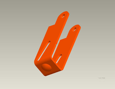
The punches are modeled using the normal part module while the hinge is modeled using the sheet metal module. Shown in the images below are the detailed drawings of the two punches and the hinge. The real image of the hinge is shown in this tutorial: 012 Window Wheel Mechanism - Part #1


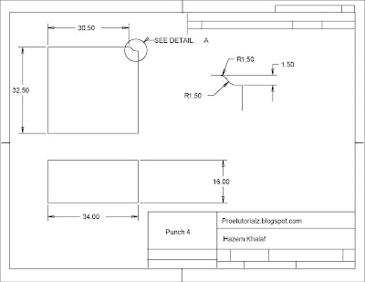
The modeling of this Hinge is done in simple 5 steps:

  1. First, the two punch tools are created by using the revolve and extrude tool and this is shown in the first two videos.
  2. The side wall of the Hinge is created using the sheet metal module.
  3. The other two walls surrounding the base are created at the edges of the base using the profile shown in the above detailed drawing.
  4. The punch forms are applied using the form feature.
  5. Some dimensions are missing and are assumed during modeling since this is not going to affect our modeling later on.


Here are the four Pro/E video tutorials showing the modeling of this Hinge:


Friday, July 17, 2009

013 Window Wheel Mechanism - Part #2

The First Hinge

This video tutorial shows the modeling of the first hinge part using Pro/E. First, there will be a video to create the punch tool and then there will be another one to create the hinge itself. That punch tool will be used to make the form or the protrusion that is in the base of the hinge.

The punch is modeled using the normal part module while the hinge is modeled using the sheet metal module. Shown in the images below are the detailed drawings of the punch and the hinge. The real image of the hinge is shown in this tutorial: 012 Window Wheel Mechanism - Part #1


The modeling of this Hinge is done in simple 5 steps:
  1. First, the punch tool is created by using the revolve tool and this is shown in the first video.
  2. The Base of the Hinge is created using the sheet metal module.
  3. The two walls surrounding the base are created at the edges of the base using the profile shown in the above detailed drawing.
  4. The punch form is applied using the form feature.
  5. Some dimensions are missing and are assumed during modeling since this is not going to affect our modeling later on.

Here are the three Pro/E video tutorials showing the modeling of this Hinge: